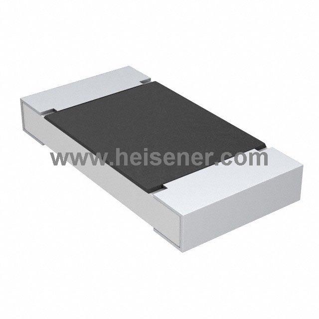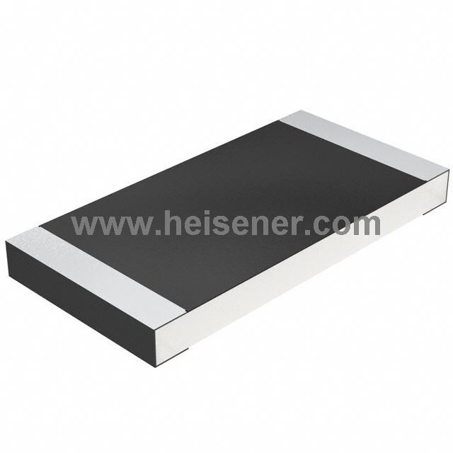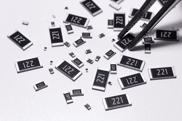
A resistor is a basic component in an electrical circuit. Its main function is to limit the flow of current. The unit of resistance is the ohm (Ω), which is the ratio of voltage (V) to current (A), expressed as R = V / I. There are many types of resistors, and this article focuses on the chip resistor.
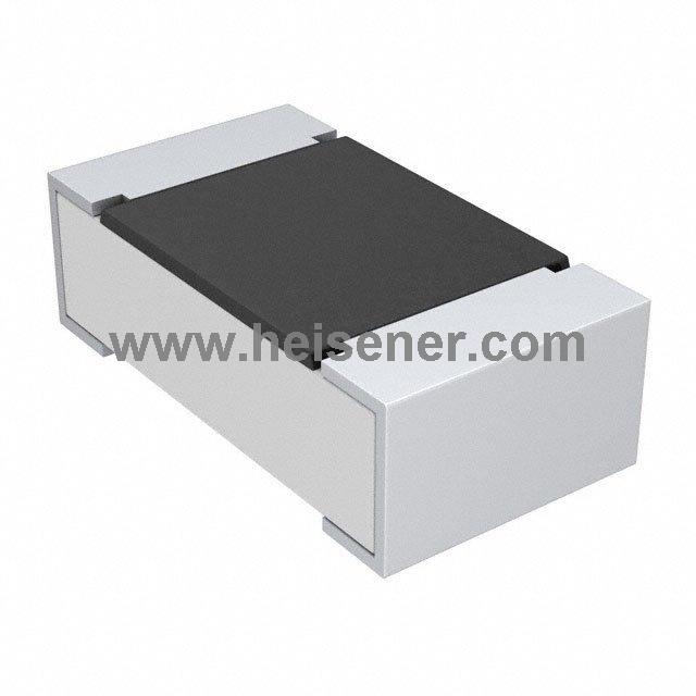
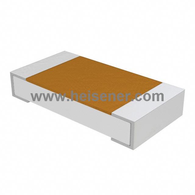
A chip resistor, also known as a SMD resistor, is an electronic component designed to be mounted on a PCB using surface mount technology (SMT). Unlike traditional through-hole resistors that need to be inserted into holes on the PCB and soldered on the other side, a chip resistor is directly placed on the surface of the board and fixed with solder paste and hot air reflow.
The chip resistor is used to control current, divide voltage, or limit current in circuits. It is usually made of a ceramic substrate, metal or thick film resistive layer, and terminal electrodes. Due to its compact size, stable performance, and suitability for automated production, it is widely used in mobile phones, computers, automotive electronics, and industrial equipment.
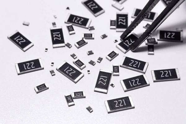
The features of chip resistors include:
Small size and light weight: Chip resistors are smaller than through-hole resistors, which helps in making electronic devices more compact.
Good electrical performance: With a larger contact area, chip resistors have lower contact resistance, improving overall circuit performance.
Excellent high-frequency characteristics: Chip resistors perform better in high-frequency applications because their physical structure helps reduce parasitic effects.
Suitable for automated assembly: Chip resistors are compatible with automated production lines, which improves manufacturing efficiency and consistency.
Heat dissipation performance: The heat dissipation of chip resistors is generally not as good as that of through-hole types, so special design considerations may be needed for high-power applications.
The naming rules for chip resistors(SMD Resistors) are mainly based on their package size, resistance value, tolerance, and material type. While the exact format may vary among manufacturers, the general naming convention follows a standard pattern.
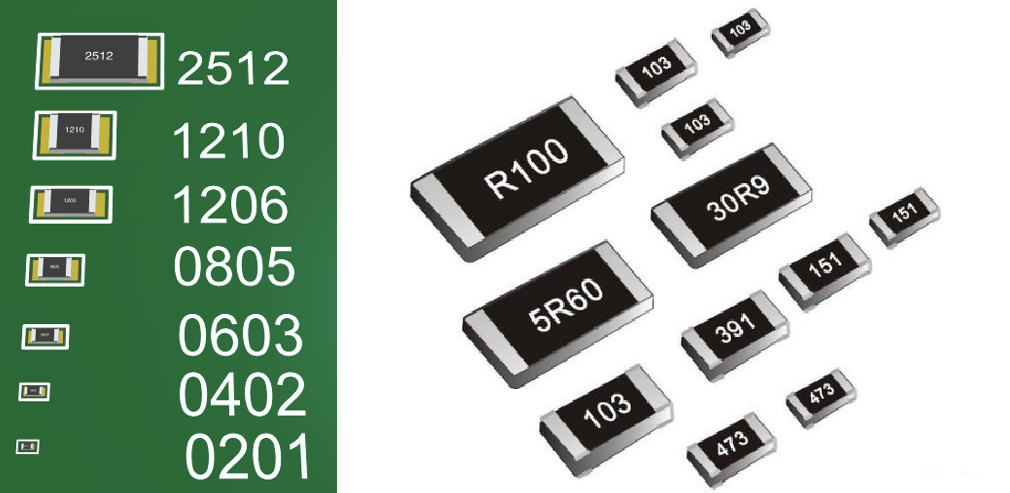
General format:
[Package Size] + [Resistance Value] + [Tolerance Code]
Example:
0805 103 J
means an 0805 package, 10 kΩ resistance, and ±5% tolerance.
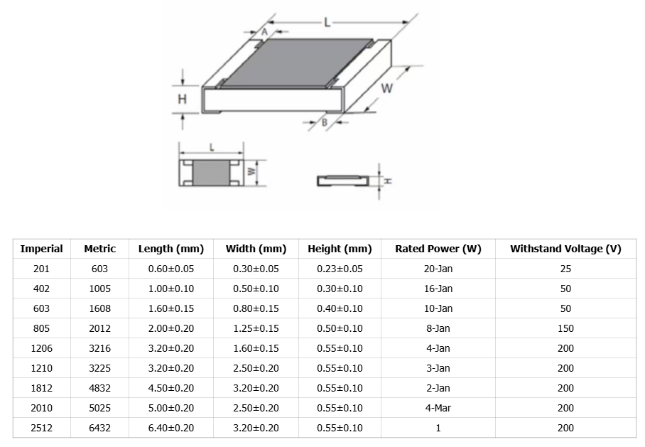
Tips: Generally, the larger the package size, the higher the rated power.
Resistance is expressed using three-digit or four-digit codes.
Three-digit code (E24 series):
The first two digits are significant figures, and the third digit is a multiplier (power of 10).
Example:
103 = 10 × 10³ = 10 kΩ
472 = 47 × 10² = 4.7 kΩ
Four-digit code (E96 series, high precision):
The first three digits are significant figures, and the fourth digit is the multiplier.
Example:
1001 = 100 × 10¹ = 1 kΩ
Codes with "R" for decimal point:
The letter R indicates the decimal position.
Example:
4R7 = 4.7 Ω
R22 = 0.22 Ω
| Code | Tolerance (±) |
| F | 1% |
| G | 2% |
| J | 5% |
| K | 10% |
| M | 20% |
0603 472 J
- 0603 → Package size: 1.6 × 0.8 mm
- 472 → Resistance: 4.7 kΩ
- J → Tolerance: ±5%
The resistance value of a chip resistor is usually marked on its surface, similar to other resistors. There are
three main marking methods, but they are not exactly the same as those of standard resistors.
(This is commonly used for rectangular chip resistors.)
In this method, three digits are printed on the resistor. The first two digits are significant numbers, and the third digit shows how many zeros follow them. For example, “472” means 4700Ω (4.7kΩ) and “151” means 150Ω.
If the value includes a decimal point, “R” is used to represent the point and counts as one of the digits. For example, “2R4” means 2.4Ω and “R15” means 0.15Ω
Like ordinary resistors, some chip resistors use color bands to show resistance values. Usually, there are four bands: the first and second bands are significant digits, and the third band is the multiplier. For example, “Brown-Green-Black” means 15Ω and “Blue-Gray-Orange-Silver” means 68kΩ ±10%
This method uses a mix of numbers and a letter (two digits and one letter).
The two digits represent a code from the E96 series, the letter represents the multiplier. For example, “51D” means 332 × 10³ = 332kΩ
A precision SMD resistor is a small surface-mount resistor with a very low tolerance. Usually, the tolerance is 1%, and the smallest can be 0.01%. Its temperature coefficient can be as low as ±5ppm/°C. These resistors are used in precision instruments, communication devices, and portable electronics.
Many people ask if it is possible to tell the difference between 5% and 1% tolerance resistors without testing. The answer is yes, by looking at the resistor codes printed on the surface.
How the codes work:
5% chip resistors usually use 3-digit codes. The first digits show the value, and the last digit shows how many zeros to add. For resistors below 10Ω, the letter “R” shows the decimal point. 1% precision resistors use 4-digit codes, where the first three digits are the value and the last digit shows the number of zeros. “R” is also used for values below 10Ω.
In short, the printed code can help identify the resistor’s tolerance: 3-digit codes mean 5%, and 4-digit codes mean 1%. This makes it easy to distinguish between standard and precision SMD resistors without measuring.