Many systems require battery power. Batteries can be used to provide backup power in the event of a power outage, but are mostly used in mobile devices - as large as electric cars and as small as hearing AIDS. In all battery-powered systems, power efficiency is key. In the case of the same running time, the lower the power efficiency, the larger the battery will be, and the higher its cost. In addition, the battery provides different voltages depending on the state of charge. This requires special power converters to adjust the variable voltage provided by the battery to the stable voltage required by the system's electronics. Today, most battery-powered systems use rechargeable batteries rather than non-rechargeable primary batteries. This requires a battery charger to be included in the system. This article covers various battery charging architectures and some innovative new use cases. Of course, power conversion efficiency is a top priority.
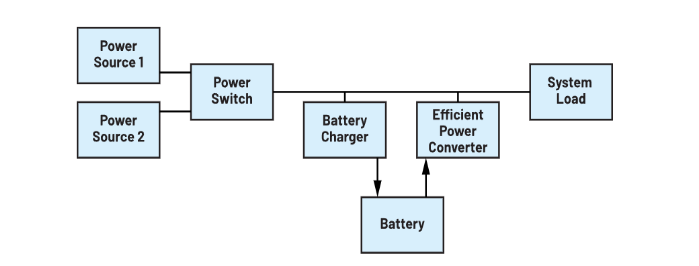
Figure 1 shows a system diagram of a battery powered system. Although the specific implementation will vary depending on the use case, in general, all systems will contain the main functional modules shown in the figure. There is some kind of power supply voltage in the system, which supplies power to the system. This connection usually needs to be switchable. If the power supply is a wall AC power converter, then unplugging the low-voltage power cord has the same effect as switching the power switch to the off position in Figure 1. This power path management is necessary to avoid additional circuits connected to the power supply consuming valuable battery power. In addition, there is a potential second power source in Figure 1. The power switch module enables switching between the power streams of power supply 1 or power supply 2. For example, Power supply 2 can be a USB 5V power supply.
Figure 1. Simplified system diagram of a battery powered system

This power supply is then converted to safely charge the available battery and/or directly power the system. If no input power is available, the energy stored in the battery will power the system via a very efficient switching mode power converter.
Power efficiency of battery powered systems
Battery charging usually does not require very high power efficiency. In addition to energy harvesting, most battery-powered systems get enough power to charge the battery. For example, when a phone is connected to a charger, most people don't usually care about the exact efficiency of the charging process.
However, in an energy harvesting system, power efficiency during charging is critical. Ultimately, the higher power efficiency during charging directly leads to a smaller energy collector size, which reduces system costs and can reduce system size.
However, all battery powered systems pay attention to the power conversion efficiency when the battery is discharged. In the case of the same system operating time, the higher the power conversion efficiency in this process, the smaller the battery capacity required.
The efficiency of this power conversion stage to generate the voltage required to load from the battery needs to be further evaluated. One is full load conversion efficiency, which provides information on how long a system can operate under a nominal load, and the other is light load efficiency, which is important for many systems. This is the power conversion efficiency at a very small load. Battery-operated smoke detectors, for example, operate sustainably for years during the low-load current smoke detection phase until smoke is detected and an alarm is issued. The alarm is initiated by a high current, but the power efficiency at this stage has little to do with the point at which the battery needs to be replaced.
When the load power consumption is very low, the static current IQ is related to efficiency. The lower the static current, the better. This static current, together with the switching scheme, determines the low load efficiency. Figure 2 shows a typical efficiency curve with and without light load efficiency mode. The light load efficiency mode is blue curve, and the fixed switching frequency mode is black dashed curve. Many power conversion circuits use this mode to improve light-load efficiency. Usually, the way it works is to stop using a constant switching frequency and only produce a few switching pulses when the output voltage drops slightly. In the time between these bursts, the power converter turns off many functions to save power. These low-power modes may vary slightly from IC to IC in terms of specific architecture, but this particular mode always achieves very high efficiency under light loads.
Figure 2. Power conversion efficiency of the ADP2370 step-down regulator under two conditions: one when the low-load power-saving mode is activated, and the other when a fixed 600 kHz switching frequency is used at all loads.

As shown in Figure 2, the efficiency difference at 1 mA output load is quite large. When the power saving mode is activated at a light load of 1 mA (even as low as 100 μA load), the power conversion efficiency is 50%. At a fixed switching frequency of 600 kHz that does not activate the power-saving mode, the efficiency is only about 15%.
Power conversion challenge
As mentioned above, power conversion efficiency is very important in battery-powered systems. Battery powered systems can be selected from all existing types of topologies. One of the commonly used topologies is a four-switch buck-boost converter. Many systems require a 3.3V supply voltage, powered by a single lithium-ion battery. Such batteries provide a nominal voltage of 3.6V, but in the late discharge state, they only provide a voltage between 2.8V and 3.0V. In order to extend the operating time of the system, we need to use as much battery power as possible. In a 3.3V system, when the lithium-ion battery is fully charged, we need to lower its voltage from 3.6V to 3.3V.
However, when the battery discharge is near the end, we need to boost the 2.8V to 3.3V. This requires a step-up circuit. There are many different types of buck-boost circuits. Suitable topologies include transformer-based flyback, two-inductor single-ended Primary inductor Converter (SEPIC), and four-switch buck-boost topologies, to name a few. The four-switch buck-boost topology is usually chosen because it has the highest power conversion efficiency compared to the other two topologies.Figure 3 shows the concept of a four-switch step-up topology
Figure 3. Example of a four-switch buck-boost power converter, such as the LT3154 buck-boost DC-DC converter

Using two lithium-ion batteries in series, rather than one, avoids the step-boost topology altogether. In this case only a simple step-down power converter is required. However, we need to pay extra effort and cost for a second battery. In addition, charging two batteries is more challenging than charging just one. When the two batteries are used in series, the maximum voltage is 7.2V. Power converters require a semiconductor process with a higher voltage than the typical maximum 5.5V process. This is not a problem, but the semiconductor cost of DC-DC power converters may be slightly higher.
Choose the right battery charger
There are many battery charger ics on the market. A battery charger is a device that provides voltage and current in a safe manner, thus charging the battery. When choosing an integrated circuit, you first need to decide whether to use a linear charger or a switch charger. Linear chargers are like linear regulators that can only reduce the available voltage. The input current is roughly equal to the output current.
For example, if the depleted battery voltage is 0.8V and the available system voltage is 3.3V, the linear charger must be stepped down to 2.5V. If the charging current is 1 A, the linear charger will consume 2.5 W of power in the form of heat. This is feasible, but if the system voltage is 12 V, the power consumption will be 11.2W. Therefore, for applications where the charging current is low and the system voltage is close to the battery voltage, a linear charger is a reasonable choice.
For all other applications, an on-off charger is recommended. Most battery charger ics on the market are switch mode battery chargers. These are classic switching power supply (SMPS) devices with special features that support battery charging. It can be charged with either constant voltage or constant current, or sometimes both, and special features are provided to ensure safe charging. This can be a timer to detect whether the connected battery is defective, or it can include a temperature sensor to limit the battery temperature during charging to avoid thermal runaway in different situations. Another popular feature is the safety check between the battery pack and the battery charger, which monitors whether the battery connected to the system is licensed.
Figure 4 shows a standalone SMPS battery charger solution. The MAX77985 is used to realize the functions of step-down SMPS battery charger and power path switch. The power path switch is an essential feature in most applications. Once the battery is fully charged, it disconnects the input voltage rail from the battery to prevent battery power consumption through circuits that may be connected to the input power line. In addition, the solution has a digital I2C interface that can change certain Settings of the charger IC as well as for telemetry purposes. To make the battery charger as flexible as possible, the digital interface supports setting different battery types and battery sizes.
Figure 4. Simplified circuit diagram of MAX77985 independent battery charger

Among the many different features, one in particular is worth noting. The integrated power switch in the MAX77985 not only charges the battery in buck mode, but can also be used to boost the battery voltage to a higher system voltage. In a way, this battery charger is a combination of a system power converter and a pure battery charger.
Battery powered devices require many different electrical functions. Some products provide only basic functions, while others have most functions highly integrated in a single integrated circuit. This product, called a system power management integrated circuit (PMIC), is particularly popular in battery-powered applications. There are various reasons for this. One reason is that many battery-powered systems are quite small and therefore require compact system solutions. The second reason is that each individual IC has a certain static current, and the IC always consumes some power when it is turned on or off, which eventually depletes the battery power. In most cases, combining many different integrated circuits into a single PMIC device can reduce the static current of the system.
Over the past 20 years, the advent of high-capacity lithium-ion batteries has changed the face of battery-powered systems. Many integrated circuits can be used to charge and discharge these batteries efficiently. Nowadays, in order to increase the capacity per unit weight and volume, speed up the charging speed of the battery, and ensure the safety of the battery, the industry is carrying out a lot of research on the future battery structure. With the continuous development of battery technology, the innovation of battery charging and discharging integrated circuits will also be endless.
About US
Heisener Electronic is a famous international One Stop Purchasing Service Provider of Electronic Components. Based on the concept of Customer-orientation and Innovation, a good process control system, professional management team, advanced inventory management technology, we can provide one-stop electronic component supporting services that Heisener is the preferred partner for all the enterprises and research institutions.
