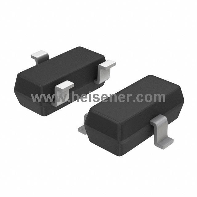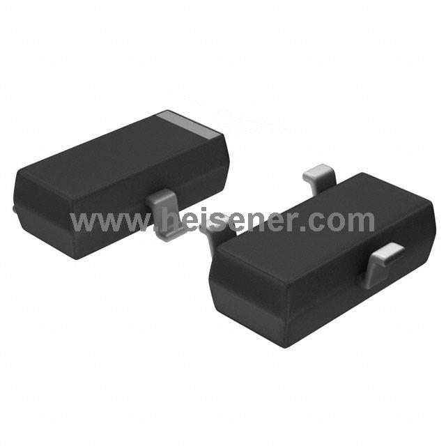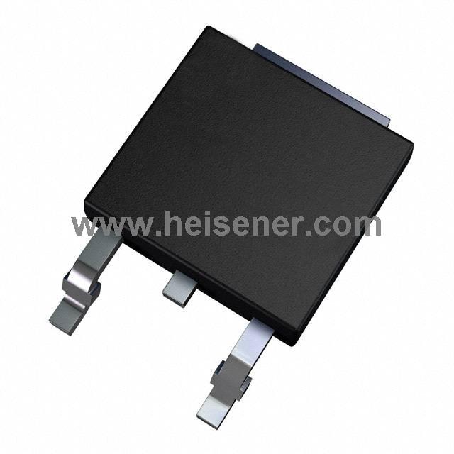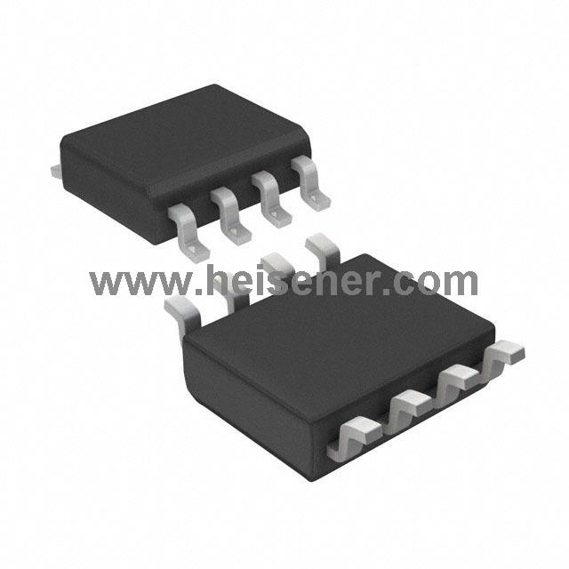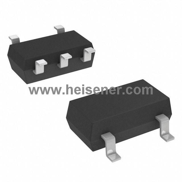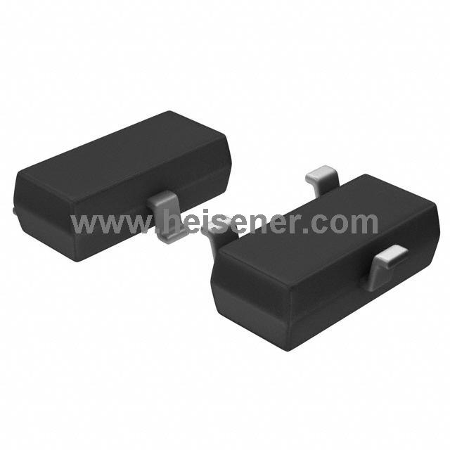
MMBT3904 is a common NPN small-signal transistor. It uses a SOT-23 SMD package. It supports up to 40V VCE and a maximum collector current of 200mA. The device is made of plastic or epoxy material, which allows it to withstand higher temperatures. With its small size, stable performance, and low cost, it is widely used in relay drivers, LED control, power switches, motor pre-drivers, and audio/signal amplifier circuits. Its complementary PNP transistor is MMBT3906, which can be paired for more complex circuit designs.
MMBT3904 works by controlling the base current. When there is no base current, the transistor is in cutoff, and the path between collector and emitter is off. When a base current is applied (Ib ≤ 5mA), the transistor enters the active or saturation region. It can allow up to 200mA to flow through the collector and emitter to drive loads. The current gain enables it to act as a current-controlled switch.
The DC current gain (hFE) can reach up to about 300. The transistor can operate in three states: cutoff (off), active region (linear amplification), and saturation (fully on). So it can be used both in digital switching circuits and analog amplification applications. MMBT3904 is a classic and reliable small-signal transistor in many electronic designs.
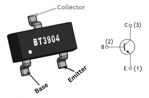
B (Base): Controls the transistor's ON/OFF state by receiving a small input current
E (Emitter): Current flows out through this pin; usually connected to ground in NPN circuits
C (Collector): Current flows in from the load; the main current-carrying terminal
| Type | Specification |
| Collector-Emitter Voltage (VCEO) | 40 V |
| Collector-Base Voltage (VCBO) | 60 V |
| Emitter-Base Voltage (VEBO) | 6 V |
| Continuous Collector Current (IC) | 200 mA |
| Collector Cutoff Current(Max) | 50nA |
| Vce Saturation (Max) @ Ib, Ic | 300mV @ 5mA, 50mA |
| Power Dissipation | 200–350 mW |
| DC Current Gain (hFE) | 100–300 |
| Transition Frequency (fT) | 300 MHz |
| VCE(sat) | 0.2–0.3 V |
| VBE(on) | 0.65–0.85 V |
| Operating Temperature | -55°C ~ 150°C |
| Package | SOT-23-3 (TO-236) |
Silicon Epitaxial Planar NPN Transistor
Miniature SOT-23 Plastic Package
For Surface Mounting Circuits
Tape and Reel Package
The PNP Complementary Type is MMBT3906
General Purpose
Compliant to RoHs
The Thermal Resistance Is 403℃/W
Its Rise Time Is 35nsc
Suitable for Portable Equipment
Small Load Switch Transistor with High Gain and Low Saturation Voltage
Signal Processing
Switching
Amplification
Commercial Grade
Drive modules
Home Appliances & TV Applications
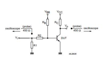
This circuit diagram is a test circuit for the MMBT3904. It is used to measure the transistor’s switching and amplification characteristics.
The input signal, Vi, passes through voltage divider resistors R1 and R2. They provide base current to the DUT (Device Under Test). RB is the base pull-up resistor. It controls the base bias voltage. RC is the collector load resistor. It is used to measure the collector current and output voltage Vo.
An oscilloscope is connected to the input and output via a 450 Ω probe. It allows real-time observation of the input and output waveforms.
When Vi is positive, base current flows, turning on the transistor. Collector current flows through RC, and Vo drops (typical NPN behavior). When Vi is zero or negative, the transistor turns off. Collector current is nearly zero, and Vo is close to VCC.
By observing the waveforms, you can evaluate the MMBT3904’s switching speed, saturation, and gain.
The MMBT3904 has many direct or near-direct replacements because it is a common NPN small-signal transistor. The closest equivalents are devices with the same electrical characteristics and the same SOT-23 package, such as SMMBT3904, MMBT3904LT1, and MMBT3904LT3.
There are also compatible NPN transistors with similar specifications, such as BC847, BC817, MMBT2222A, and S8050. These parts may offer higher current capacity or slightly different gain ranges, but they work well in most general switching, signal amplification, and MCU-level drive circuits.
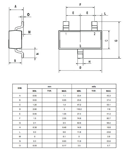
MMBT3904 uses the common SOT-23 surface-mount package. It has a small footprint. The package offers good thermal performance and reliable assembly. The following section shows the detailed package dimensions:
Click to MMBT3904 Datasheet PDF
Before connecting the MMBT3904, you should first confirm the pin direction. The SOT-23 MMBT3904 has three pins. Pin 1 is the emitter (E), pin 2 is the base (B), and pin 3 is the collector (C). Before soldering or wiring, check the pin order according to the marking on the device. This helps you avoid reversing the pins.
When wiring, connect the base resistor first. Send the signal or control output to the base through a current-limit resistor. This controls the base current and protects the transistor. Then, connect the emitter to ground (common for NPN). Next, connect the collector to one side of the load, and connect the other side of the load to the positive power supply. In this setup, when the base gets current, the transistor turns on. Current flows from the power supply → load → collector → emitter → ground.
For testing, it is better to start with low voltage or low current. This helps you make sure there is no short or wrong wiring. Then increase to normal levels. By checking the output, you can see whether the MMBT3904 works correctly. For example, when the base gets a positive signal, the load should turn on. When the base has no signal, the transistor should turn off. Step by step, you can finish the correct connection and testing.
MMBT3904 is a small-signal NPN transistor in a SOT-23 SMD package. It is used for switching and low-power amplification.
Pin 1 = Emitter, Pin 2 = Base, Pin 3 = Collector.
Common alternatives include SMMBT3904, MMBT3904LT1, BC847, MMBT2222A, and S8050 (depending on application).
Yes. It works well as a general NPN switch for loads such as LEDs, small relays, and logic-level control.