As early as more than a decade ago, 400V battery systems were introduced in electric vehicles, and now we see the industry migrating to 800V systems, mainly to support DC fast charging. With increased voltages and lessons learned from 400V systems, designers are now focusing on enhancing the performance of high-voltage protection circuits and improving reliability. They are reevaluating existing solutions that use fuses, contactors, or relays to find solutions that are more responsive, robust, and reliable, such as hot and electronic fuses (E-Fuse).
One leading solution is electronic fuses based on silicon carbide (SiC) technology.SiC provides high operating voltage, high operating temperature, low on-resistance, low turn-off leakage current, and durability to overvoltage transients. The solid-state design of the electronic fuse eliminates reliability issues associated with arcing, mechanical wear, contact jitter, and position welding. The energy saver hardware used to drive the contactor coil is no longer required. Electronic fuses enhance system-level performance through their configurability, controlled on and off, on-board diagnostics, and durability against high voltage transients.
Resettable design, no maintenance required
With an all-sic design, electronic fuses are unmatched in their response to short circuits, hundreds of times faster than hot fuses. Because of this characteristic, electronic fuses are a natural complement to hot fusion-based protection solutions. Although a hot fuse provides robust and reliable circuit protection, it is not resettable. It's a single-use device, like the gunpowder in an airbag.
In severe cases, the hot fuse is used as a safety measure to cut off the power supply to the system. Once it detonates, it needs to be replaced. Changing components in a high-voltage system is not as simple as it is in a 12V system. A 400V or 800V system voltage is much higher than the 60V limit that is generally considered safe in the automotive industry and can only be safely repaired by a qualified service technician. Fortunately, due to their configurable tripping characteristics, electronic fuses as a system level package solution are more sensitive to overcurrent than hot fuses, ensuring that they trip first to avoid triggering hot fuses. A big advantage of electronic fuses compared to today's solutions is their resetability, which helps electric vehicle owners save time, expense and hassle associated with vehicle maintenance.
Robust DC circuit protection
Circuit protection in HVDC systems presents unique challenges. Unlike AC systems, where zero crossing helps extinguish the arc, DC systems do not have such a zero crossing. To combat this, high-voltage electric vehicle relays and contactors contain additional complex features to safely extinguish the arc. However, the arc can still erode the contacts, leading to reliability issues such as high contact resistance or position welding.
Electronic fuses, on the other hand, can safely disconnect the direct current circuit without creating an electric arc. The type of induced energy that causes arcing in relay-based solutions is also present in the protective circuit of the electronic fuse, so the electronic fuse solution needs to absorb this energy when it interrupts the current.
The main difference is that the electronic fuse responds quickly, reducing peak currents to several orders of magnitude lower than traditional solutions. Since the induced energy is proportional to the square of the current, a reduction in the peak short-circuit current will also result in a significant reduction in the allowable energy. This also reduces line stress and reduces potential downstream failure loads.
Electronic fuse demonstrator with configurable trip characteristics
The Microchip assisted electronic fuse technology demonstrator shown in Figure 1 can be used by designers developing automotive high-voltage electronic fuses or solid-state relays. Six hardware models are available with 400V and 800V options and 10A, 20A, and 30A current ratings, supporting individual or parallel SiC MOSFETs from 15 mΩ to 40 mΩ for evaluation of RDS(on).
Figure 1:Microchip's auxiliary electronic fuse technology demonstrator
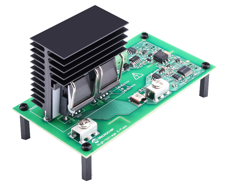
The control and protection circuit of the electronic fuse is powered by a 12V system. The demonstrator is equipped with a LIN communication interface that supports a direct connection to the 12V battery, while waking up from sleep mode via LIN activity or from the switch battery output of the control module.
As shown in the time-current characteristic (TCC) curve in Figure 2, electronic fuses include three overcurrent detection methods, ranging from slightly overcurrent to extremely high short-circuit current. The TCC curve defines the fusion-like behavior of the electronic fuse, which responds slowly to low overcurrents and quickly to high overcurrents.
It can be easily adjusted to protect the line and load. These three detection methods can be easily configured through software or the LIN interface. The blue detection method on the far left uses the junction temperature estimation algorithm to describe the tripping behavior. This algorithm uses current measurements, ambient temperature measurements, RDS(on) of SiC MOSFETs, and thermal design characteristics to estimate the junction temperature of SiC MOSFETs.
The response time varies with the magnitude of the overcurrent. The middle line segment represents a detection method using a single current measurement with a fixed response time. The line segment on the far right represents a hardware-based detection method that can be configured by software. This approach leverages the PIC® MCU's kern-independent peripherals (CIPs), which include comparators, fixed reference voltages, digital-to-analog converters, and configurable logic units configured as SR latches. This ensures that signal propagation times are as short as a few hundred nanoseconds, allowing immediate detection of short circuits and protection of high-voltage systems.
Figure 2: Time-current characteristic curve of 400V and 20A electronic fuse models

In addition to fusion-like behavior, electronic fuses can also assume the function of electromechanical relays. Just as the relay coil and its high-voltage contacts are electrically isolated from each other, there is also an isolation barrier between the control signal of the high-voltage electronic fuse and the high-voltage terminal. The electronic fuse has relay-like flexibility and can be connected to the system as a high-side output that feeds the positive side of the high-voltage battery to the load, or as a low-side output that provides a return path for the load to the negative side of the high-voltage battery, as shown in Figure 3.
Figure 3: Electronic fuse system level configuration

High voltage short circuit performance
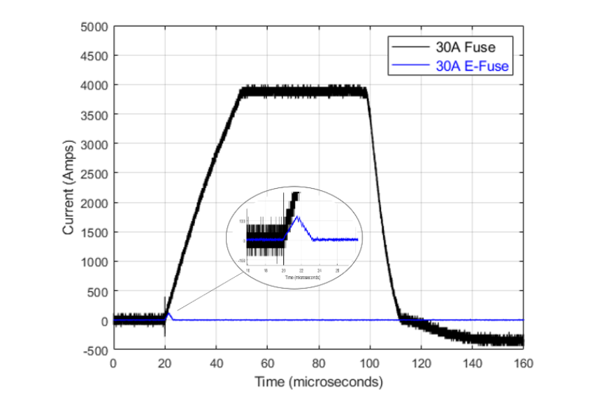
To really demonstrate the difference in response time between an electronic fuse and a conventional automotive high-voltage fuse, we subjected each fuse to a short circuit under similar test conditions of 450V and approximately 3µH line inductance. The resulting waveform is shown in Figure 4. The black waveform is the current flowing through the high-voltage fuse during the test. Within 30 µs, the current reaches the measuring device's limit of 3800A, and the high voltage fuse is blown after 50 µs. Based on the test parameters, the peak current is estimated to exceed 6000A. However, as shown in the blue waveform, when using an electronic fuse, the current before tripping is only 128A. This represents a significant reduction in allowable current and minimizes stress on wiring and downstream loads.
It gives system designers the option to optimize wiring to reduce weight and cost. In some cases, a low allowable current of an electronic fuse will be the difference between a towing state (a fault that causes high current stress causing permanent damage to the hardware) and a recoverable fault (allowing the system to reset automatically and the driver to continue operating the vehicle).
Figure 4: Current waveforms of electronic and high voltage fuses
In addition to electric vehicles themselves, supporting infrastructure such as DC fast charging stations or microgrids that power charging stations would also benefit from electronic fuses. The advantages offered by electronic fuses are not limited to automotive applications.
Applications using fuses and contactors can benefit from some of the topics explored as well as other advantages, including on-board current detection, which enables further system-level integration and optimization. Non-vehicle-mounted applications utilize common source and anti-series SiC MOSFET configurations and may require higher current capabilities than those provided by the demonstrator. Fortunately, the design extensions are simple and can be adjusted for the SiC power modules provided in the common source configuration.
As our focus on performance, safety and reliability continues to grow, electronic fuses as a circuit protection solution will continue to evolve as a preferred approach, just as we have seen 12V systems move from fuses and relays to protected solid-state drives and, more recently, to low-voltage electronic fuses.
About US
Heisener Electronic is a famous international One Stop Purchasing Service Provider of Electronic Components. Based on the concept of Customer-orientation and Innovation, a good process control system, professional management team, advanced inventory management technology, we can provide one-stop electronic component supporting services that Heisener is the preferred partner for all the enterprises and research institutions.